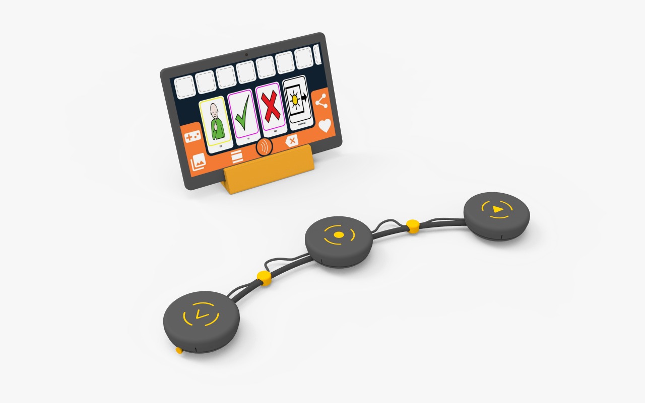
Worm Accessible Keyboard
The Worm accessible keyboard allows the user to interact with a PC, tablet or smartphone using 3 commands, which enables the selection of items on the screen with OTTAA Project's screen scan functionality (Move right or left and select).
The device has been specifically designed for motor impaired people who have difficulties in their fine motor skills. It is compatible with Android, Windows, MacOS and Linux.
Materials
- Bale wire 2mm x 590mm.
- Black synthetic hose 4x7mm x 600mm.
- Limit switch (x9).
- PCB - Logitech M170 Mouse.
- Battery holder case.
- Switch ON/OFF.
- 3.5mm male Jack and stereo female socket (x2 each).
- Bipolar cable D: 4mm, L: 50cm.
- O-shaped ring, D:50mm (x3).
- Self-tapping screw 2.5mm.
- Screw M8 (75mm).
- Nut (M8).
- 3D printed C-type clamp (3 parts). Link: M, N, O.
- 3D printed Accept Button (5 parts). Link: P, Q, R, S, T.
- 3D printed Right Button (3 parts). Link: U, V, W.
- 3D printed Left Button (3 parts). Link: X, Y, Z.
- 3D printed Cable Connector (x2). Link: AA.
- 3D printed End Caps (x2). Link: AB.
Procedure
3D Printing
Parts M, N, O, P, Q, R, S, T, U, V, W, X, Y, Z, AA and AB 3D printing settings:
- Material: PLA.
- Temperature of the hotend: 210-215 °C.
- Temperature of the print bed: 50-60 °C.
- Top and Bottom Layers: 3.
- Perimeter Shells: 3.
- Infill: 25%.
- Support: 75°(only X.stl).
Dismantle Mouse Logitech M170
- Take out the mouse PCB and remove the limit switches from the left, right and scroll click. Assemble the Accept Button
- Weld the ON/OFF switch terminals to a cable. Introduce the switch into part P as shown in Figure 12. Then apply pressure to fit part S to the switch as shown in Figure 13.
- With the help of a cable, connect 3 limit switches in a parallel connection, and then weld the cable to the PCB. Place the limit switches in part P as shown in Figure 14 and secure the joint with glue.
- Weld the terminals of a 3.5mm Jack plug to a bipolar cable, and introduce it in part P as shown in Figure 15.
- Weld the terminals of the battery holder case to a bipolar cable. Introduce it in part P as shown in Figure 16. Part P has 2 protruding ends; first, in a diagonal direction, fit one of the protruding ends into the hole of part P, then straighten it and apply pressure until the second protruding end locks.
- Introduce the metal spring over the PCB as shown in Figure 17.
- Place the O-shaped ring on the depression/indentation of part R, cut it to size (Figure 18) and glue it.
- Insert a AA battery in the battery holder case, then the battery cover (R) on part P, and fix it with the 2.5mm screw (Figure 19).
- Fit part T with part Q as shown in Figure 20, and optionally use a few drops of glue to secure the joint.
- For the final assembly of the Accept Button, part P has 3 slots and part Q has 3 protruding ends. In a diagonal direction, match one of the protruding ends with one slot and apply pressure. Then straighten, match and apply pressure on the second protruding end and repeat for the third one (Figure 21).
Assemble Right Button
- Connect 3 limit switches in a parallel connection with a wire and weld them to a Jack plug and the stereo output cable. Place them in part U, and optionally use glue to assure them.
- Place the 3.5mm Jack plug in part U.
- Attach with silicone the metal spring inside the part U.
- Put the O-shaped ring in the depression of part U, cut it to size and glue it.
- Fix part W inside part V, and glue it to secure the joint.
- For the final assembly of the Right Button, part U has 3 slots and part V has 3 protruding ends. In a diagonal direction, match one of the protruding ends with one slot and apply pressure. Then straighten, match and apply pressure on the second protruding end and repeat for the third one.
Assemble Left Button
- Repeat the assembly instructions for the Right Button but with parts X, Z y Y respectively.
Assemble the C-type Clamp
- Put the M8 nut inside part M (Figure 22).
- Put part N on the head of the M8(L:75mm) screw, glue part O to another M8 nut and screw it onto the other end of the screw (Figure 23).
Assemble flexible tube
- Insert the bale wire through the black synthetic hose (Figure 24).
Final assembly
Slip the flexible tube through the different parts in the following order (Figure 25):
Right button (RB). Part AA.
Accept button (AB). Part AA.
Left button (LB).
Then connect the 3.5mm Jack plug. Finally, insert parts AB in the ends of the flexible tube (Figure 26).
Blueprints
The technical drawings of the parts to be printed are shown below: