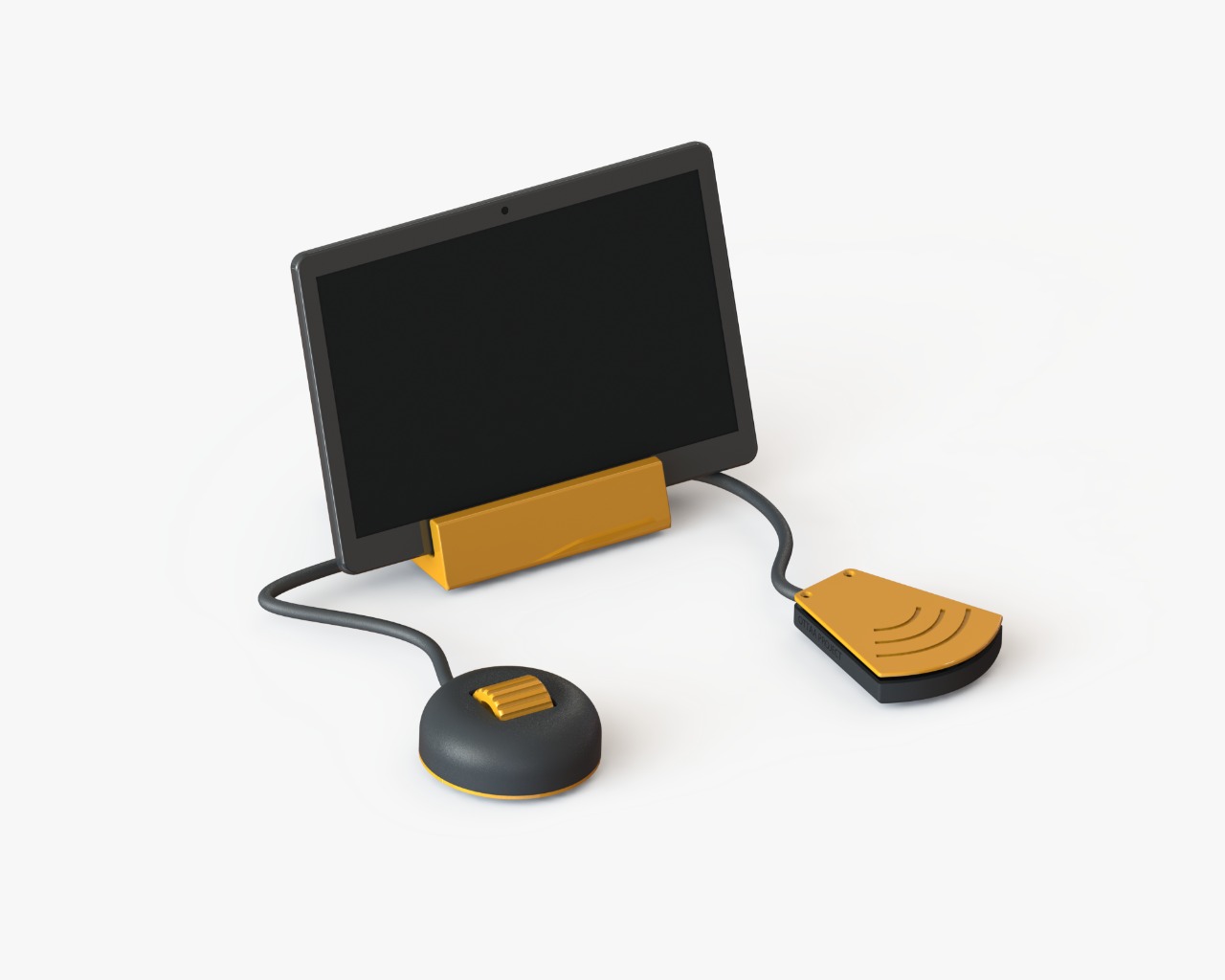
Scroll & Press
The Scroll & Press device imitates the functions of scrolling and left clicking of a traditional PC mouse, which enables the selection of items on the screen with OTTAA Project's screen scan functionality. The device has been specifically designed for motor impaired people who have difficulties in their fine motor skills. It is compatible with Android, Windows, MacOS and Linux.
Materials
- High quality sound cable (25cm).
- 2 limit switches.
- 4mm x 3 self tapping screw.
- Non-slip weatherstrip. D: 4mm, L: 270mm.
- 4-wire cables 25cm long (USB like).
- PCB Genius DX110/120.
- OTG adapter.
- Glue and silicone.
- 3D printed scroll wheel. Link: F.
- 3D printed scroll housing (2 parts). Link:G, H.
- 3D printed push button (2 parts). Link: I,J.
- 3D printed lectern (2 parts). Link: K, L.
Procedure
1. 3D Printing
- Parts F, G, H, I, J and K 3D printing settings:
- Material: PLA.
- Temperature of the hotend: 210-215 °C.
- Temperature of the print bed: 50-60 °C.
- Top and Bottom Layers: 3.
- Perimeter Shells: 3.
- Infill: 25%.
- Support: 75°(only B.stl).
2. Dismantle Genius DX 120 Mouse
- Take out the mouse PCB and remove the left and right click limit switches.
3. Assemble the push-button
Place the two limit switches on the base of the 3D printed push button (J).
Using bipolar cables connect them in a parallel connection and weld them to the PCB. The push buttons have to work in normally opened mode. (Figure 7, Figure 8, PCB connection).
Place I on J and fix it with two self-tapping screws (Figure 9).
4. Assemble the scroll wheel
- Insert the mouse wheel in the 3D printed wheel (F) (Figure 10, Figure 11).
- Place F at the base of the scroll (G).
5. Assemble the scroll
Fit the encoder’s hole with the protruding end of F. Fit the encoder onto part G.
With the help of a soldering iron, connect the PCB to the encoder using a 4-wire cable, then secure the welding and wires with silicone.
Fit the scroll housing cover (H) with the base (G).
Place the non-slip weatherstrip on the underside of G, fix it by pressure and optionally use glue to strengthen the joint.
Place the self-tapping wood screw to fix the G to H joint. Assemble the tablet stand
Place the PCB on the base of the tablet stand (L), ensuring the correct positioning of the bipolar and 4-wire cables.
Fit the base of the lectern with the tablet stand housing (K) by pressing and fixing it with a self-tapping screw to close the tablet stand.
6. Blueprints
The technical drawings of the parts to be printed are shown below: